Anatomy of a Rectifier- by Tim House
|
 |
How to check if you rectifier is working in situ---Kristian Storli
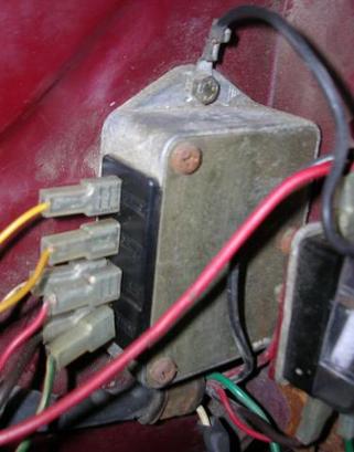
The best and simplest way to see if it is working is to test it's output. Hook it up in the bike, set your meter to read DC volts in the correct range and put the leads on the battery. If the rectifier/regulator is good, then the meter should read a few volts higher when the engine is running, than it does when the engine is off. A healthy Rally battery will read 5.5 to 6.5 volts with the engine off, and a healthy rectifier should feed it about 6.5 to 9.5 volts, depending on the revs, with the engine on.
If you find low DC output, you have confirm it's the rectifier and not the AC input. Pull the two yellow wires off, set your meter to measure AC volts, and put it between the two yellows. I don't remember exactly what the unloaded AC output should be at that point, but I'm guessing that your meter will read somewhere between 4 and 12 volts at idle, which should be ok.
The AC voltage output over around 8 or 9 volts is why those resistors are inside that box, and why using a bridge rectifier without a 6v zener diode (or some other form of voltage regulation) is bad idea.Using a bridge rectifier by itself with the battery as the only voltage regulator may protect your bulbs, but is also likely to boil your battery. The battery will fill out the "valleys" in the system, but offers no self protection for the "peaks".
Hope this helps.
Kristian Storli
BAR ITALIA CLASSICS
14767 Calvert St.Sherman Oaks, CA, 91411818-997-0082
www.baritaliaclassics.com
Rebuilding a Rally Rectifier by Tim House
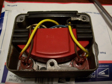
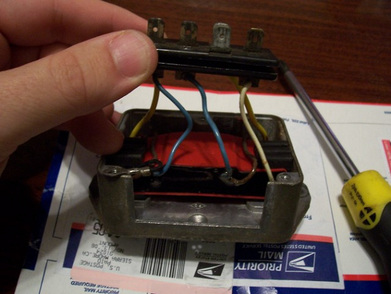
Here of photo's of Tim House rebuilding a rectifier. I hope to get in touch with him soon to see how his rebuild went. Whatever the result it's cool to see the innards of the rectifiers. At the bottom of this photo there appears to be two resisters that are installed in parallel with the old rectifier unit. You can see both the yellow wires from the spades to diodes, and the brown wires from the diodes to the rectifier. Resisters help take the peaks off the fluctuating AC current coming from the stator. Without them, you may boil your battery or blow out your bulbs. If they are capacitors, they would help fill in the valleys of AC current.
|
 |
|
What Tim did was to solder the blue and brown wires together, and connected them to the AC in leads on the bridge rectifier. Then connected the negative lead on the rectifier to the black ground wire, and the positive lead on the rectifier to the white wire, (DC output).
|
 |
